The latest addition to the collection of old classic computers came from the same place as most of my other computers, eBay. A listing for two Atari ST computers a 520ST and 1040ST.
The eBay description said that the 520 was working but the 1040 did not power on and both had been stored in an attic for several decades. The pictures were dark and grainy but it was possible to make out that the computers were the later STFM models which included a floppy drive, TV modulator and internal power supply. I placed a £70 bid, not expecting them to sell for so little, they normally sell for at least £100 each. As it turned out I was the highest bidder and several days later two Atari ST computers arrived in the post.
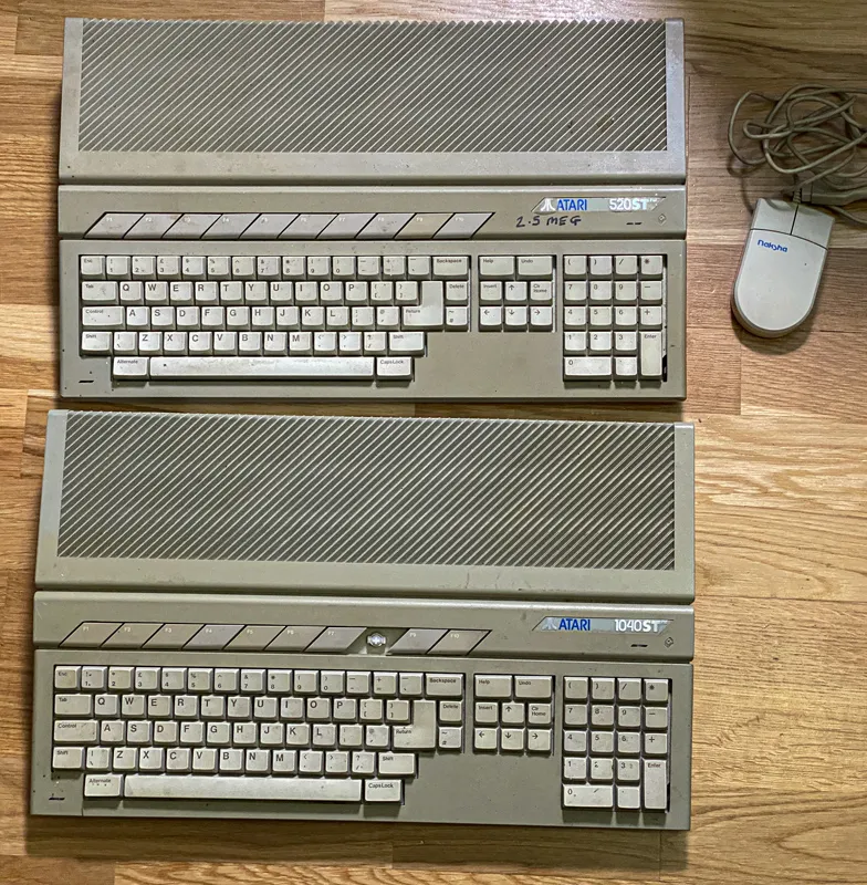
Atari 520 and 1040 STFM
A short history of the Atari ST
The Atari ST was a line of personal computers released by Atari Corporation in the mid-1980s. They were notable for their advanced graphics and sound capabilities. The ST gained a strong following in Europe, particularly within the gaming and music communities as the built-in MIDI ports made it a popular choice for digital music production.
The 520 STFM, released in 1986, featured 512KB of RAM and an internal floppy disk drive. The “F” denoted the inclusion of the floppy drive, while the “M” indicated the built-in RF modulator, allowing direct connection to a television.
The 1040 STFM, introduced shortly after, doubled the memory to 1MB which helped with more demanding applications and multitasking. Like the 520 STFM, it included a built-in floppy drive and RF modulator.
Both models ran on the Motorola 68000 CPU and used the GEM (Graphics Environment Manager) operating system, which provided a graphical user interface that was ahead of its time.
In many ways the Atari ST was similar to the Commodore Amiga, using the same 68000 CPU and having comparable amounts of memory. The main area where the Atari ST lacked compared to the Amiga was in graphics and multitasking.
First Inspection
The two Ataris arrived well packaged, wrapped in bubble wrap and cardboard. As I unwrapped the computers I noticed a rattling coming from inside which was disconcerting. First inspection showed that both computers were covered in a thick layer of grime and dust.
The 520 looked to be in reasonable condition, the floppy drive had been replaced with an aftermarket model and some of the keys were different colours suggesting that the keyboard was not completely original.
The 1040 had its original floppy drive but it was missing the F8 key on the keyboard. This was visible in the photos for the eBay listing so I had already found a suitable replacement key from another seller.
Both computers would need stripping down so they could have a deep clean and a chance to inspect the internals for damage. First on the workbench was the 520.
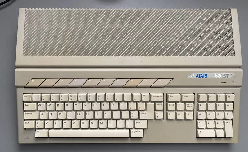
The Atari 520 STFM
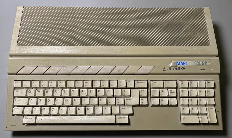
The 520 before cleaning
The first job was to take the computer apart and see where the rattling was coming from. I tried to remove all of the screws on the bottom but found that two of them kept spinning.
The top came off with those two screws still in place revealing the plastic posts on the top half of the case had sheared off. There were several bits of plastic floating around inside the case which I put to one side so they could be glued back once I found where they came from.
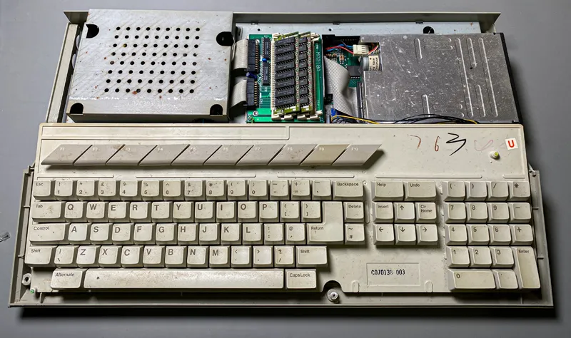
Inside the Atari 520 STFM
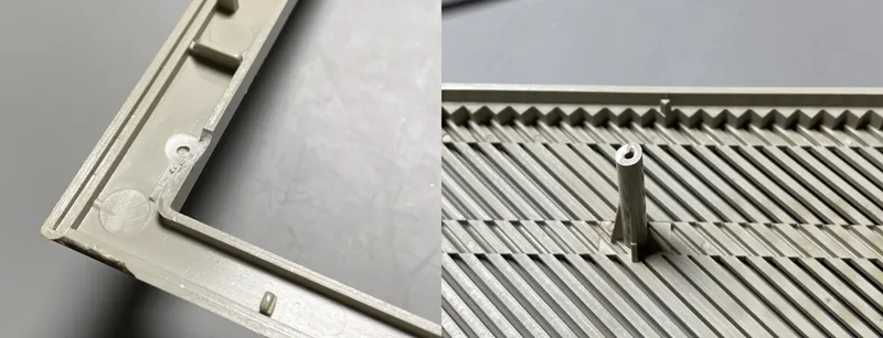
Damage on the 520 Case
Behind the keyboard was a memory upgrade board with two 1Mb 30 pin SIMMs. This would have brought the total memory available up to 2.5Mb.
The cover for the power supply had rust around the holes so the computer had seen water at some point in its life.
Once everything was disassembled the case was given a good scrub with hot water and soap to remove the dirt. There were some black marks made using a marker pen which were removed using methylated spirits.
The case still has a yellow tint that you find in many plastic items from this period. This happens when plastic is exposed to ultraviolet light, heat, humidity, or other extreme temperatures and environments. The yellowing can be reversed by coating the plastic in hydrogen peroxide cream, commonly used by hairdressers for bleaching hair, and exposing it to UV light. I have used this technique in the past but as I do not have a UV lamp big enough it is a process reserved for the summer when I can use the sun as a UV light source.
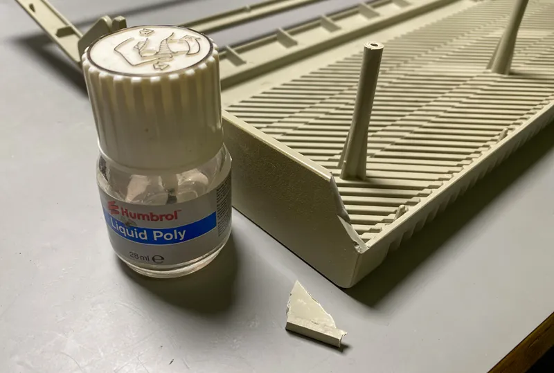
The broken off fragments of plastic that were found inside the case were glued back into place using Humbrol liquid poly adhesive. Liquid Poly adhesive is normally used for building plastic models but it also works well for repairing old plastic cases as it melts the surface of the plastic so when the two parts are pushed together they form a strong bond that can be almost invisible.
Repairing the Case
The Keyboard
The keyboard had a collection of dust, food and other assorted nasties under the keys so that would need to be stripped down and cleaned thoroughly.
All of the keys were carefully removed from the keyboard and soaked in water overnight before being cleaned one at a time with a sponge and warm water. The keyboard was disassembled and the key switches and membranes were removed and wiped down to remove any dust. The plastic housing for the keyboard was cleaned in soapy hot water to remove the dried on food and bits of dead skin that had accumulated.
Once the keyboard was clean and dry it was reassembled.
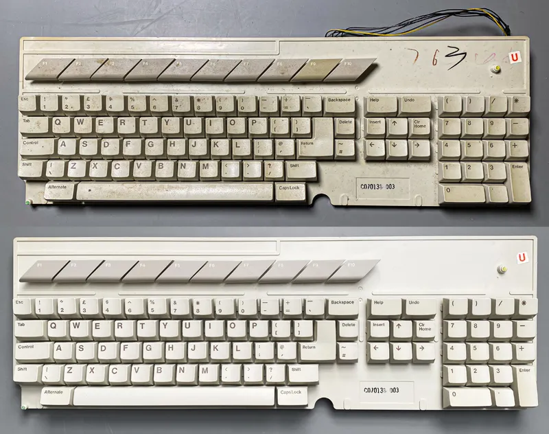
Keyboard before and after cleaning
The Power Supply
The 520 STFM power supply was sold as working so once it was removed from the computer I plugged it into the mains supply and switched it on. The 5V and 12V outputs were showing 5.2V and 11.8V on the multimeter so it did appear to be working.
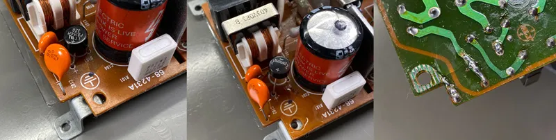
A closer inspection of the power supply showed that resistor R4 had some cracking around the casing. The resistor is a metal film type and the damaged appeared to only be in the ceramic coating so it was probably caused by thermal stress or the same shock damage that had caused the plastic case to break in so many places. Either way it would be better to replace it with a new resistor.
I unsoldered the resistor and checked its resistance and found that it was 260 ohms. The colour bands on the outside were brown, brown, brown which should be 110 ohms so something wasn’t right. I found the schematic for the power supply to find the correct value and that showed R4 should be a 2W 330R resistor. Whether the wrong value was installed in the past or the colour banding had faded from overheating I am not sure but I replaced the resistor with a 330R version and tested the voltages again. It showed as being 5.2V and 12.1V so the voltages were now closer to what they should be.
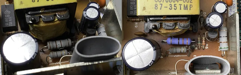
520 PSU repairs
Capacitor Testing
On old electronics the electrolytic capacitors have a tenancy to degrade and occasionally explode when they get old. On the BBC Micro refurbishment I replaced all of the electrolytic capacitors but for the Atari I wanted to try and keep as many of the original components as possible. Instead of replacing the capacitors I unsoldered each one in turn and tested them on an LCR meter.
When capacitors degrade their capacitance drops and their Equivalent Series Resistance (ESR) increases.
An LCR meter provides accurate measurements of capacitance, resistance, and inductance at various frequencies, offering a more detailed measurement than a simple multimeter. Since ageing capacitors can exhibit an increased ESR which could cause power loss and instability in circuits, checking both capacitance and ESR is essential for assessing their health.
For each capacitor the ESR and capacitance were measured and checked against the specifications for that capacitors value and voltage rating. There are four outcomes for an LCR test.
-
Capacitance within tolerance & low ESR → The capacitor is in good condition.
-
Reduced capacitance but low ESR → The capacitor may still function but has degraded. Consider replacing it.
-
High ESR, even if capacitance is normal → The capacitor is failing and should be replaced.
-
Both capacitance and ESR far off spec → The capacitor is likely faulty and should be replaced immediately.
All of the capacitors in the power supply were surprisingly within the capacitance and ESR specifications so they did not need to be replaced.
The Memory Expansion
The 520 STFM came with a memory expansion card and two 1Mb 30 pin SIMMs that would have increased the memory from the original 512Kb to to 2.5Mb.
The expansion card did not have a manufacturers logo or name on it but after doing some research it appears to be an Xtra-Ram Deluxe from Marpet Development, or Frontier Software depending on how old it is. The Xtra-Ram Deluxe can take up to four 1Mb SIMMs but for that to work the internal RAM has to be disabled.
I was planning on giving the 520 STFM away and keeping the 1040 STFM as it was in better condition and had a later revision motherboard so I carefully removed the memory expansion from the motherboard returning it to its original stock configuration. The expansion boards were put to one side to be installed in the 1040 once I have four 1Mb SIMMs to fit in it.
Reassembly and Testing
With all of the components cleaned and repaired it was time to reassemble the computer. The motherboard and power supply were screwed into the base, the floppy drive was attached and the keyboard connected.
Before putting the top back on I decided to power up the computer to see if it worked. Switching it on showed a grey screen for a few seconds and some floppy drive noises before the TOS desktop appeared on the monitor.
The mouse cursor moved when I moved the mouse which was a good start but after putting a FAT formatted floppy disk into the drive and clicking on the disk icon all that happened was some motor noises and a prompt showing an error reading the disk.
To check if the problem was with the floppy drive or the floppy controller I took the drive out of the 1040 and put it into the 520. The drive that came with the 520 was a third party drive while the 1040 was an original Atari drive.
With the drive from the 1040 installed the 520 opened the floppy disk and ran the SysInfo program that I had copied onto the disk. This showed that the problem was with the original floppy drive.
One issue with the 1040 drive was that it didn’t want to eject floppy disks. Dissembling the drive showed that the top of the mechanism was buckled down in the middle. Evidently the 1040 had been dropped as well, probably when they were bundled together in the parcel. A bit of light force was needed to bend the mechanism back into shape after which the disks would eject properly.
The floppy drives in both computers are going to be replaced with Gotek USB drives so the broken drive will not be an issue but for now the working floppy drive was left in the 520.
The next test was the keyboard. I loaded a text editor and started typing. All of the F keys and alternate numbers along the top row would not work. Looking on the schematic all of the faulty keys were connected to two PCB traces that went into pins 13 and 14 on the keyboard controller IC.
The keyboard was disassembled and on close inspection of the PCB it revealed a crack in the board, probably from an impact, which had broken several PCB traces. To fix this the solder mask was cleaned off the area around the copper traces and wires were soldered across the breaks.
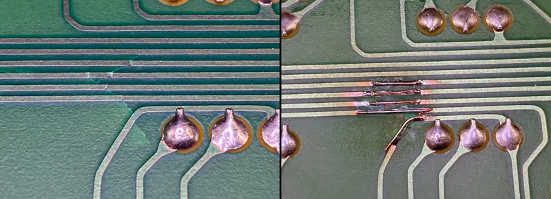
Repairing the Keyboard PCB
The keyboard was reassembled and plugged back into the computer. Running the same tests as before showed the problem had been fixed and all of the keys now worked.
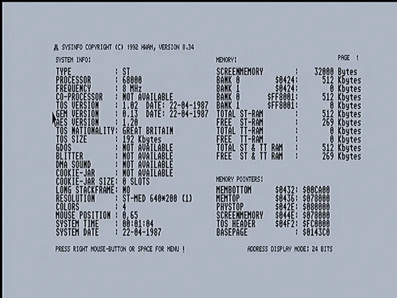
520 SysInfo screenshot
With the keyboard and floppy drive now working the computer was reassembled.
The 520 cleaned and repaired
The Atari 1040 STFM
Most of the 1040 restoration was the same as the 520. The case was in an overall better condition than the 520 with the only damage being a split in the top along the front edge and a corner missing on the back edge. Both were easily repaired using Humbrol glue.
The motherboard was fairly clean with only a bit of dust. The floppy drive had the issues described above and with the floppy drive going into the 520 that left the 1040 without a drive for the moment.
The keyboard worked but was missing the F8 key. I managed to find a seller on eBay who was selling individual keys for the ST so a replacement was purchased and installed on the keyboard.
The Power Supply
While removing the power supply I noticed that the fuse had blown. The eBay description said that the 1040 would not power on so this looked like the reason. I replaced the fuse and plugged the power supply into the mains. As soon as I turned it on the new fuse immediately blew meaning there was a bigger problem with the power supply.
The first step was to test all of the capacitors. On a power supply of this age the most common fault is an electrolytic capacitor that has failed and shorted internally. As with the 520 power supply I removed each capacitor in turn and checked it on the LCR meter. They all measured as working and within specifications.
The next component to test was the bridge rectifier. The rectifier was unsoldered and tested using the diode setting on my multimeter. A bridge rectifier is made up of four diodes and should measure a voltage drop of around half a volt in one direction across each pair of wires and no current flow in the other direction. On this bridge rectifier there was a direct short across three of the pins, two of which were connected to the AC input which would explain why the fuse blew when it was switched on.
The specifications for the bridge rectifier were 1.5A and 400V. I replaced it with a 2A 600V version which should give it a bit more resilience.
All of the other components on the power supply were tested to make sure nothing else had failed. Everything else still worked so I replaced the fuse again, plugged the power supply into the mains and turned it on. This time it worked with 5V and 12V on the output pins.
Repairing the 1040 PSU
With the power supply fixed I reassembled the 1040 and turned it on. I borrowed the floppy drive from the 520 so I could boot into the desktop. The mouse and keyboard appeared to be working perfectly and I could load programs from a floppy disk.
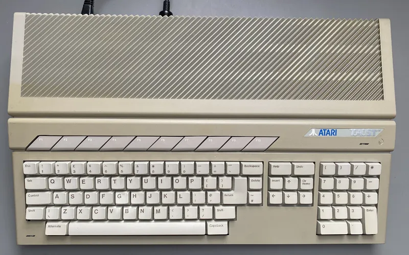
The 1040 STFM after repairs
With both Atari ST computers repaired and restored the 520 will be given away to a friend and the 1040 kept for future upgrades and projects.

David L.
Very nice job, congrats! Envy you your skills, particularly soldering ones…
My 1040STFM that I own since about 1990 needs case and keyboard cleaning too, and the original FDD (Epson SMD-480L) isn’t reading floppies; I already cleaned heads with alcohol but it didn’t help.. I’ll take it out again today and try to clean and lubricate head moving rail area..but the FDD isn’t dirty inside at all..I’ll see if this rail cleaning will make any difference. I don’t feel replacing with new FDD (Atari-modded newer 1.44MB type) because it would require slight case cutting to fit the FDD and I want my ST to be as close to original as possible.. anyway, thanks for reading and very motivating pics!
David