18 November 2026
 41
 25 minutes read
This is the fourth instalment in a series on restoring and upgrading a BBC Micro Model B computer from the 1980s.
In Part 1, I cleaned the computer, repaired the power supply and replaced potentially problematic capacitors, allowing the computer to power on and display the boot screen.
In Part 2, I repaired a memory fault that was causing graphical glitches and stopping software from running correctly.
In Part 3, I added a floppy drive and SD card adapter to load and save programs on the computer.
My plan is to use the BBC Micro as a learning platform for the 6502 processor. As a part of that I want to use some of the many programming tools that developed for the BBC computers.
Adding the floppy drive and SD card adapter make the BBC Micro far more usable as a computer but adding the ROMs for the two drives filled up all of the remaining ROM sockets on the motherboard.
Many of the development tools came on ROMs that the user would plug into the motherboard. Some tools like Assemblers also need more RAM than is available as standard. With all of my ROM sockets full and only 32K of RAM installed I needed a way to add more of both if I want to use the BBC Micro to its full potential.
Luckily there is a solution to both the ROM and RAM problem, a sideways expansion board.
How sideways ROMs worked on the BBC Micro
The 6502 processor in the BBC Micro can only address 64K of memory at once. Acorn split that space in two: the lower 32K is RAM, and the top 16K holds the operating system (MOS). Between them sits a 16K window from &8000 to &BFFF, and this is where the “sideways” idea comes in.
That window doesn’t belong to a single chip. Instead, up to sixteen 16K ROMs can share it, with only one visible to the processor at a time. A small hardware latch at address &FE30, the ROM select register, decides which one. Write a number from 0 to 15 to it, and that ROM “slides” into view while the others drop out. The ROMs stack side by side rather than one above another, hence the name.
How the computer knew what each ROM did
Every sideways ROM starts with a standard header. It contains entry points, a type byte saying whether the ROM is a language or a service ROM, a title and version, and a copyright string that the MOS checks to confirm a real ROM is present. At power-up, the MOS pages through each socket in turn, reads the headers and builds a table of what’s installed.
From then on, the MOS works with them in two ways:
Language ROMs are full applications that take over the machine, such as BASIC, View, Wordwise or a Pascal or Forth compiler. Only one runs at a time, and you switch between them with commands like *BASIC or *WORD.
Service ROMs sit in the background and respond to calls from the MOS. When you type a star command the MOS doesn’t recognise, it offers it to each ROM in turn until one claims it. The same mechanism handles *HELP, workspace allocation at reset, and selecting a filing system.
This design is what made the machine so expandable. A disc filing system, a network interface, a toolkit of programming utilities or a machine-code monitor could all be added just by plugging in a chip. The new commands were then available the moment the computer was switched on, with nothing to load from tape or disc.
Sideways expansion boards
The Model B had five ROM sockets on the motherboard, under the keyboard. One held the OS ROM, a second held BBC BASIC, and the others were free for whatever the owner wanted to add.
Five sockets soon proved too few. A typical enthusiast might want BASIC, a DFS, a word processor, a spreadsheet, a toolkit and a monitor all at once. The ROM select latch could already address sixteen ROMs, so third-party companies such as Watford Electronics, ATPL and Solidisk sold sideways expansion boards that took the total up to 16 sockets. These typically plugged into one of the existing ROM sockets, with a lead connected to the ROM select signals on the motherboard.
Many boards also accepted static RAM chips in some of their sockets. This sideways RAM behaved just like a ROM, but its contents could be loaded from disc and changed at will. That made it popular for running ROM images without burning an EPROM, for software development, and for use as printer buffers or extra workspace. With a small backup battery, the RAM kept its contents when the power was off, effectively giving users rewritable ROMs. The idea was so successful that Acorn built sideways RAM into the later BBC B+ and Master series as standard.
Finding a Sideways expansion board
What I needed was a sideways board that had space for ROMs and RAM. It took several months of searching, but I eventually found exactly the board I needed on eBay.
The Watford Electronics 12 ROM board is a sideways ROM board with space for twelve ROMs or eleven ROMs and two 8K RAM chips. Combined with four ROM sockets on the motherboard it gives the BBC Micro space for a full complement of 16 ROM chips or 15 ROM chips and an extra 16K of RAM bringing the total RAM up to a massive 48K!
The board was designed to be solderless, plugging into the ROM socket where the OS ROM normally sits, and the ADC socket near the top of the motherboard. There are sockets on the sideways board for the OS ROM and ADC chip. A short cable and two pin socket connects to jumper S21 on the motherboard.
There is space on the board for a NiCad battery that keeps the two RAM chips powered when the computer is turned off, effectively turning the RAM into electrically erasable ROMs or EEPROMS.
The Board Arrives
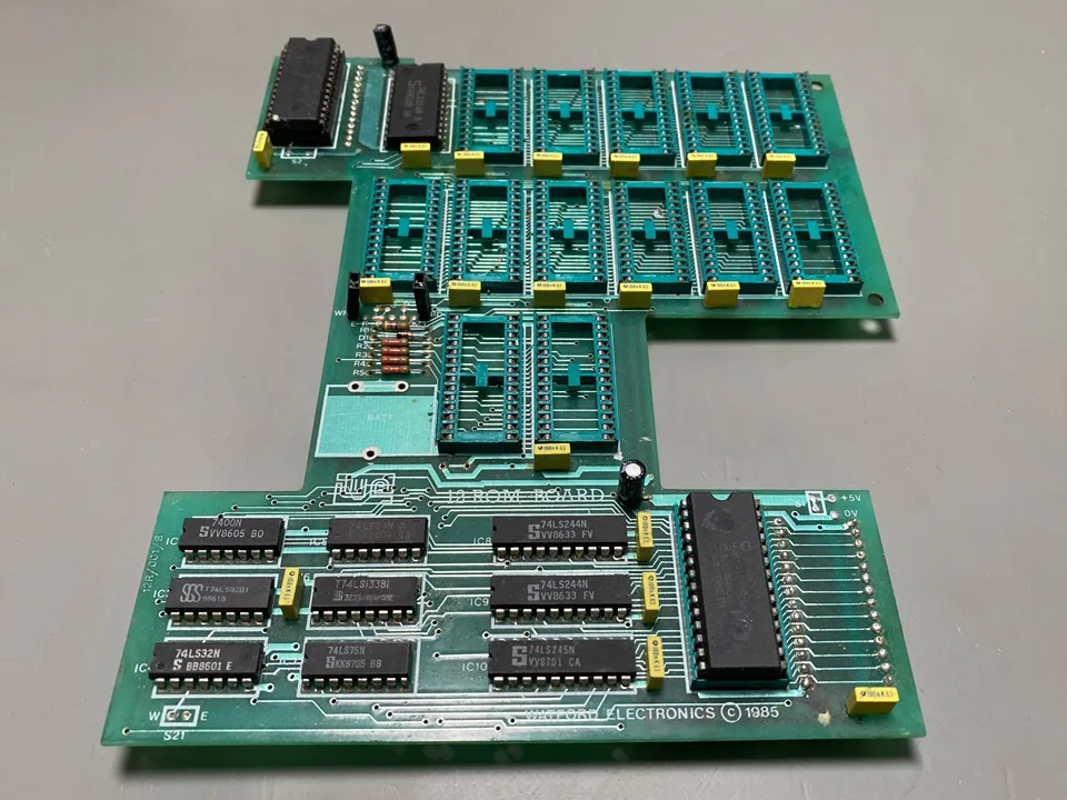
The Watford Electronics 12 ROM board
A few days after buying the board it arrived boxed up and wrapped in bubble rap. On first inspection the board appeared to be in good condition. It had an ADC and OS ROM already installed, and it looks like the battery was never installed. This is good as those batteries are notorious for leaking and destroying the circuit board and anything else the blue goo touches.
There was the usual 40-year-old dust and flux residue that you expect from electronics of this period. The first step was to remove the two chips from their sockets and give the whole board a good clean in flux cleaner.
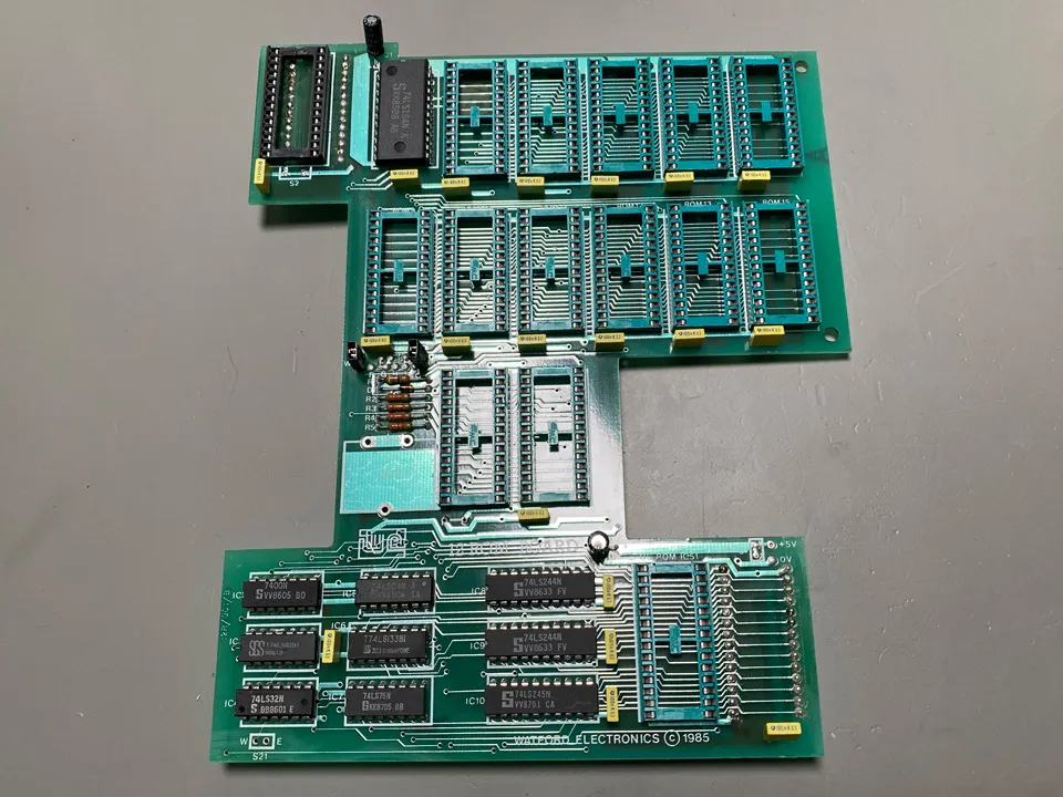
After a good clean
Once the board was clean I checked the power pins for shorts or high current draws and tested the two electrolytic capacitors. The capacitors were still well within spec so they did not need replacing. Some of the solder joints on the sockets looked a bit dry, so I applied some flux and reflowed them with a soldering iron.
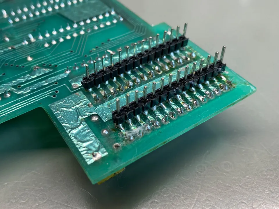
Reflowing the solder joints
The cable for the S21 jumper was missing. It looked like the previous cable had been cut off, so I removed the wire remains and soldered a new cable with connectors on the end.
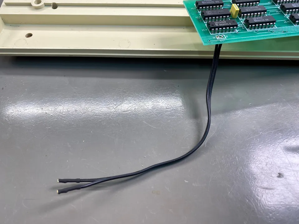
New cable for the S21 header
Assembly
I removed the OS ROM, BASIC ROM and ADC chip from the BBC Micro and installed them in the sideways expansion card. The OS ROM and ADC that came with the card were put to one side in case they are needed in the future.
The BASIC ROM was installed in socket 15, which is the highest priority socket. This is the one that will boot first when the computer is switched on.
According to the instruction manual for the board, installing it was simply a case of lining up the header pins on the bottom with the OS ROM and ADC sockets and press down. When I tried this the first problem I found was two of the power connectors that supplies 5V and Ground to the motherboard were in the way. Not a problem I thought, and I tried bending the 5V connector down out of the way. It promptly snapped off flush with the motherboard.
To fix the power cable problem I soldered cables directly to the motherboard for the 5V and Ground wires and used inline connectors on the cables. This will allow me to disconnect them in the future without needing to remove the sideways expansion card.
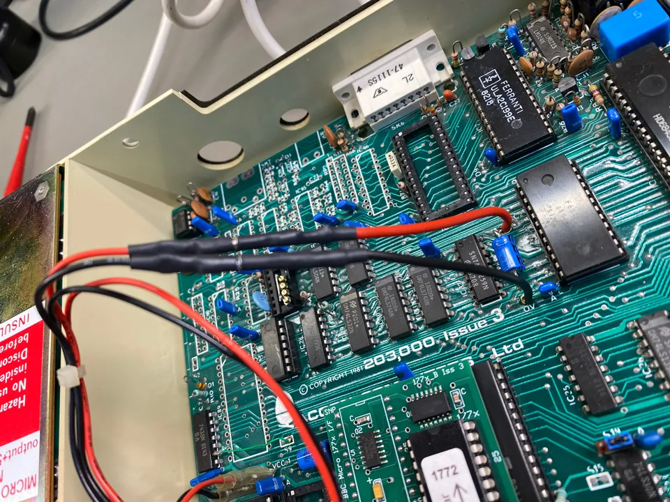
Fixing the power cable
With the power cables fixed I tried again to fit the sideways board down onto the motherboard. The next problem I found was the capacitors and jumpers on the motherboard hit the bottom of the sideways board before it could reach the two chip sockets. The manual for the board did not mention this problem, so I assume the board originally came with longer header pins that had since been replaced.
To add extra height I fitted some DIP sockets on top of the existing sockets, raising them up by 5mm. This was just enough clearance for the sideways card to fit down onto the board and get a good connection.
I installed the jumper wires onto the S21 connector, fitted the keyboard and switched the computer on. It booted up with a beep and the boot text appeared on the monitor.
Adding ROMs
The next step was to add some ROMs to the sideways board. I already had three ROMs that I could install, the disk controllers for the floppy drive and SD card adapter and the Advanced ROM Manager that allowed me to switch between the two drives.
The BBC Micro ROM Library is a good source of ROMs for the BBC range of computers. They have over 4000 ROM images covering everything from programming languages and OS tools to educational programs and games.
So far I have installed the following ROMs which should be useful when developing software on the BBC Micro.
ADE+ is a macro assembler, disassembler and editor that allows you to write programs in assembly language. It can make use of the sideways RAM when developing programs. ADE+ supports using more advanced editors such as View or Wordwise, but they need modifying to work with ADE+ so that will be a project for the future. It also needs a second ROM called ADE6500.
Exmon II (Beebug) is the best-known machine-code monitor for the Beeb. It offers memory display and editing, a disassembler, breakpoints, single-stepping, and register inspection.
HIBASIC Editor (Acornsoft) is an advanced editor for writing basic programs. It has more features than the built-in editor which make it useful for writing larger programs in BASIC.
Wordwise Plus is a word processor for the BBC Micro. This may be useful if I decide to start writing my blog posts on the BBC.
I downloaded each of the ROMs and burned them onto 27C128 and 27C256 EPROMS.
Buying second hand EPROMs on eBay can be a gamble. Some of them may have faulty cells, others may be different types of chip that with the case scrubbed clean and re-labeled as EPROMs. Of the twelve 27C128 EPROMs that I bought six worked and of the ten 27C256, nine worked.
Several of the working EPROMs had ID codes different to the markings on the chip, indicating that even though they were the correct memory type and size, they had been re-labeled as a different version. They may be slower chips labelled as faster versions, or old chips labelled as newer models.
EPROMS have to be erased using an ultraviolet eraser before they can be programmed. This takes around 10 minutes with my eraser which can become time-consuming when you are trying different ROMs.
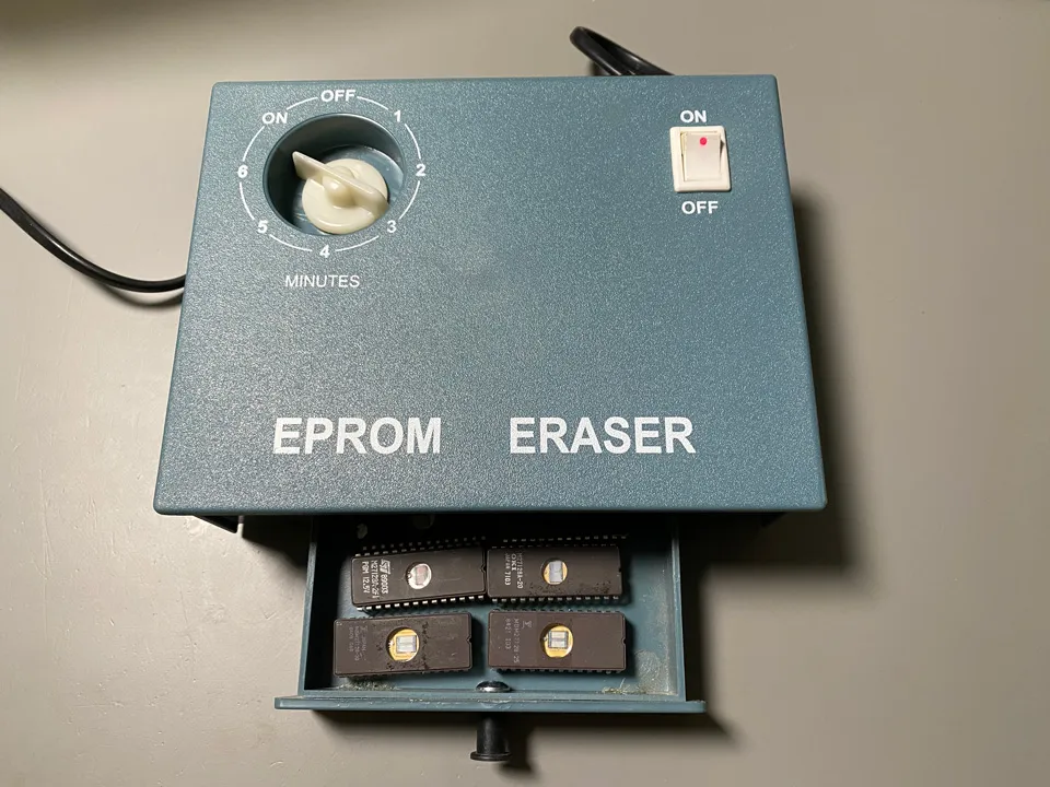
Erasing the EPROMs
ROM binary files can be written directly to the 27C128 EPROMS but with the 27C256 you have to write the ROM into the second half of the memory for it to work. If the ROM binary is exactly 16Kb you can join two files together using the CAT command on Linux to create the 32K file.
Some of the ROMs that I downloaded were slightly smaller than 16K so combining two files would put the start of the second file in the wrong place. The following Python script can be used to convert a 16K ROM into a 32K ROM. It automatically pads smaller ROM files to make them the correct size for the 27C256 EPROMs.
#!/usr/bin/env python3
"""
Turn a BBC Micro sideways ROM image (up to 16 KB) into a 32 KB image for a 27C256.

Usage:
    python3 rom_to_27c256.py input.rom output.bin           # ROM in top half, bottom half 0xFF
    python3 rom_to_27c256.py input.rom output.bin --both    # ROM in both halves

The ROM is padded with 0xFF at the END up to 16384 bytes, so its header
still starts at offset 0 (which the BBC sees as &8000).
"""
import sys

HALF = 16 * 1024


def main() -> None:
    args = [a for a in sys.argv[1:] if not a.startswith("--")]
    both = "--both" in sys.argv
    if len(args) != 2:
        sys.exit(__doc__)

    src, dst = args
    rom = open(src, "rb").read()
    if len(rom) > HALF:
        sys.exit(f"{src} is {len(rom)} bytes; a sideways ROM must be 16384 bytes or less")

    padded = rom + b"\xFF" * (HALF - len(rom))
    lower = padded if both else b"\xFF" * HALF
    image = lower + padded

    open(dst, "wb").write(image)
    print(f"{src}: {len(rom)} bytes, padded with {HALF - len(rom)} x 0xFF")
    print(f"wrote {dst}: {len(image)} bytes, ROM in {'both halves' if both else 'top half (0x4000-0x7FFF)'}")


if __name__ == "__main__":
    main()
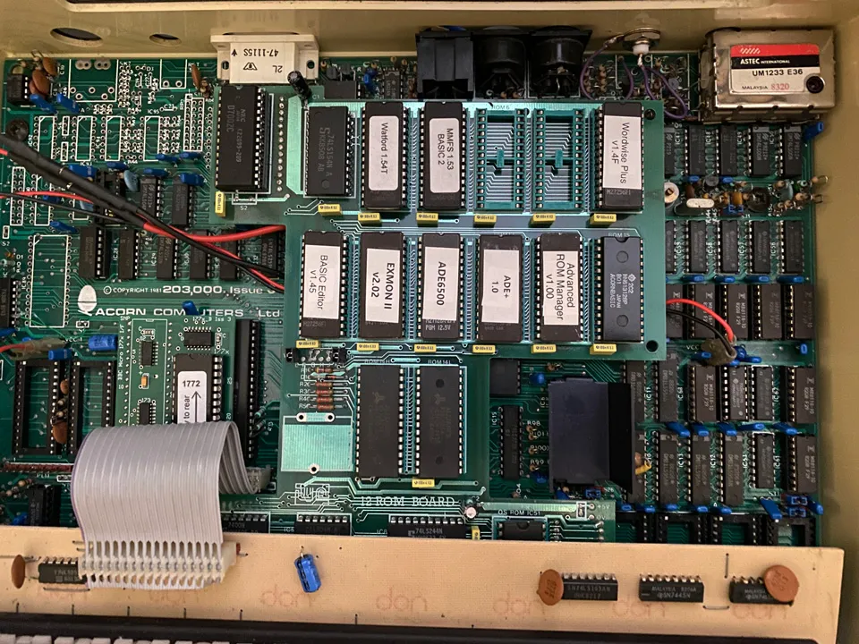
Lots of EPROMs
Adding RAM
With the ROM sockets quickly filling up the next stage was to add RAM to the sideways expansion board. The Watford board has two sockets for RAM. It uses two 8K 6462 SRAM chips which combine to make 16K of sideways RAM.
I found two Alliance Memory AS6C6264-55PCN SRAM in eBay that were unused old stock, so I purchased them and when they arrived I installed them in the sideways board.
In theory as the chips were unused and in their original packaging they should work without any problems, but I wanted to make sure both chips were functioning correctly. My BBC Micro originally came with a faulty memory chip. I didn’t want a repeat of the same problem.
The BASIC program I used to test the internal RAM was five lines of code. For the sideways RAM I needed a test program that was quite a bit more complicated.
I used the following program to test the new sideways RAM.
10 REM Sideways RAM tester - BBC Micro Model B
20 REM Pages each bank in via &FE30 from machine code in main RAM
30 MODE 7
40 bank=&70:pat=&71:ptr=&72:pg=&73:mask=&74:save=&75
50 expect=&76:actual=&77:flag=&78:ystart=&79:yfail=&7A:endpg=&7B
60 DIM code% 300
70 PROCassemble
80 PRINT "Sideways RAM tester"
90 PRINT "Scanning banks for writable RAM..."
100 found$=""
110 FOR b%=0 TO 15
120 ?bank=b%:CALL probe
130 IF ?flag THEN PRINT "  Bank ";b%;" is RAM":found$=found$+CHR$(b%)
140 NEXT
150 IF found$="" THEN PRINT "No writable RAM found.":PRINT "Check write-protect switch/links.":END
160 PRINT
170 INPUT "Bank to test (0-15, 99=all found) ",B%
180 INPUT "RAM size per bank, 8 or 16 KB ",S%
190 IF S%=8 THEN ?endpg=&A0 ELSE ?endpg=&C0
200 PRINT "WARNING: test erases bank contents."
210 INPUT "Continue (Y/N) ",a$:IF a$<>"Y" AND a$<>"y" THEN END
220 total%=0
230 IF B%<>99 THEN PROCtestbank(B%):GOTO 250
240 FOR i%=1 TO LEN(found$):PROCtestbank(ASC(MID$(found$,i%,1))):NEXT
250 PRINT
260 IF total%=0 THEN PRINT "ALL TESTS PASSED" ELSE PRINT "TOTAL ERRORS: ";total%
270 END
1000 DEF PROCtestbank(b%)
1010 LOCAL t%,e%
1020 ?bank=b%
1030 PRINT:PRINT "Bank ";b%;" &8000-&";~(?endpg*256-1)
1040 RESTORE 2000
1050 FOR t%=1 TO 6
1060 READ name$,p%,m%
1070 ?pat=p%:?mask=m%
1080 PRINT name$;TAB(24);
1090 CALL write
1100 e%=FNcheck
1110 IF e%=0 THEN PRINT "OK" ELSE PRINT'"  ";e%;" error(s)"
1120 total%=total%+e%
1130 NEXT
1140 ENDPROC
1200 DEF FNcheck
1210 LOCAL n%,a%
1220 n%=0:?ptr=0:?pg=&80:?ystart=0
1230 REPEAT
1240 CALL check
1250 IF ?flag THEN PROCreport
1260 UNTIL ?flag=0 OR n%>=10 OR ?pg=?endpg
1270 IF ?flag AND n%>=10 THEN PRINT'"  (stopped after 10 errors)";
1280 =n%
1300 DEF PROCreport
1310 a%=?pg*256+?yfail
1320 PRINT'"  &";~a%;" wrote &";~?expect;" read &";~?actual;
1330 n%=n%+1
1340 ?ystart=(?yfail+1) AND 255
1350 IF ?ystart=0 THEN ?pg=?pg+1
1360 ENDPROC
2000 DATA "All zeros  &00",0,0
2010 DATA "All ones   &FF",255,0
2020 DATA "Checker    &55",85,0
2030 DATA "Checker    &AA",170,0
2040 DATA "Address pattern",0,255
2050 DATA "Inverse address",255,255
3000 DEF PROCassemble
3010 FOR pass%=0 TO 2 STEP 2
3020 P%=code%
3030 [OPT pass%
3040 .write SEI:LDA &F4:STA save:LDA bank:STA &F4:STA &FE30
3050 LDA #&80:STA pg:LDA #0:STA ptr
3060 .wpage LDY #0
3070 .wloop TYA:EOR pg:AND mask:EOR pat:STA (ptr),Y
3080 INY:BNE wloop
3090 INC pg:LDA pg:CMP endpg:BNE wpage
3100 JMP restore
3110 .check SEI:LDA &F4:STA save:LDA bank:STA &F4:STA &FE30
3120 LDY ystart
3130 .cloop TYA:EOR pg:AND mask:EOR pat:STA expect
3140 CMP (ptr),Y:BNE cfail
3150 INY:BNE cloop
3160 INC pg:LDA pg:CMP endpg:BNE cloop
3170 LDA #0:STA flag:JMP restore
3180 .cfail LDA (ptr),Y:STA actual:STY yfail:LDA #1:STA flag
3190 JMP restore
3200 .probe SEI:LDA &F4:STA save:LDA bank:STA &F4:STA &FE30
3210 LDA &BFFF:STA expect:EOR #&FF:STA &BFFF
3220 CMP &BFFF:BNE notram:LDA #1:BNE pdone
3230 .notram LDA #0
3240 .pdone STA flag:LDA expect:STA &BFFF
3250 .restore LDA save:STA &F4:STA &FE30:CLI:RTS
3260 ]
3270 NEXT
3280 ENDPROC
The problem with sideways RAM is that it is in a different bank to the BASIC ROM. If you write a program purely in BASIC as soon as you switch banks to test the RAM the computer can no longer see the BASIC ROM and the program will crash. To get around this problem the sideways RAM tester uses functions written in assembly language that will run from the internal memory without needing to access the BASIC ROM. The program works in several stages.
First it finds the RAM banks. It probes all 16 banks by inverting a byte at &BFFF, checking that the change took, then restoring the byte. This lists which banks are writeable.
The program can test one bank or all that are found. You choose a bank, or 99 for all RAM banks found, and give the RAM size per bank (8 or 16 KB).
It runs six passes per bank. Each pass fills the whole bank, then reads it all back. &00 and &FF catch stuck bits, &55 and &AA catch shorts between adjacent data lines.
An address pattern (low byte EOR high byte) and its inverse catch address-line faults, shorted or open address pins, and aliasing.
Each pass takes a fraction of a second and failures are listed as address, value written and value read. Reporting stops if there are more than 10 errors per pass.
Running the test program on the new sideways RAM did not show any errors so it looks like I bought some good RAM.
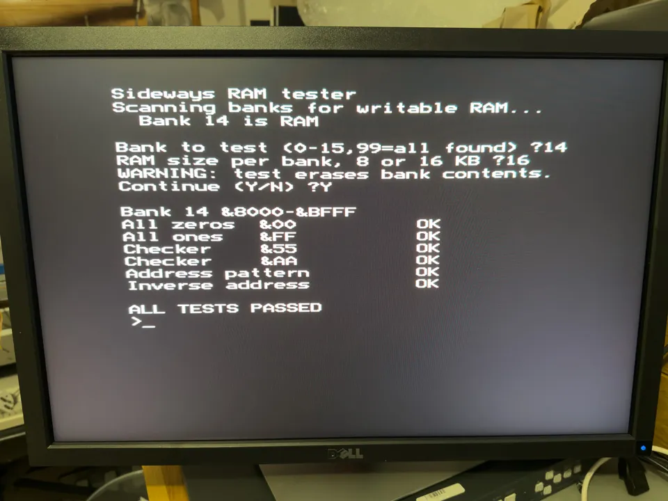
Testing the RAM
Battery Backup
More memory is useful. Memory which does not lose its state when you turn the computer off is even more useful. It allows you to develop new ROM images in memory and not lose your work when the computer resets or powers down.
The sideways expansion board has a space for a backup battery. You would normally solder a 3.6V Ni-Cad battery to the circuit board. This would charge while the computer is running and supply power to the RAM when the computer is off.
I wanted to add a battery backup to the sideways board but as I mentioned earlier in this blog post, the internal batteries do have the problem that when they get old or discharge too low they will start to spill their insides out all over the computer. The chemicals released are extremely corrosive and have killed many old computers over the years. They eat through the PCB traces and destroy components leaving the computer difficult if not impossible to repair.
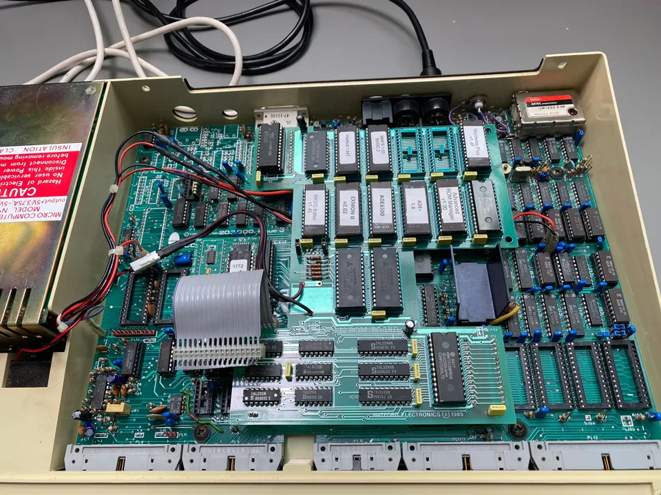
Cable for the external battery pack
As I would prefer my circuit boards to stay clean and corrosion free I decided not to solder a battery directly onto the sideways expansion board. Instead, I found a three cell AAA battery holder and fixed it to the underside of the case in the space in front of the power supply. I used three Nickel Metal Hydroxide or Ni-MH batteries which are better for the environment compared to Ni-Cad cells and have a higher capacity.
Putting the batteries outside well away from the motherboard means the batteries can be removed and replaced without taking the case apart. If they do decide to spill their internals it will end up on the desk or the underside of the plastic case where it will do less damage.
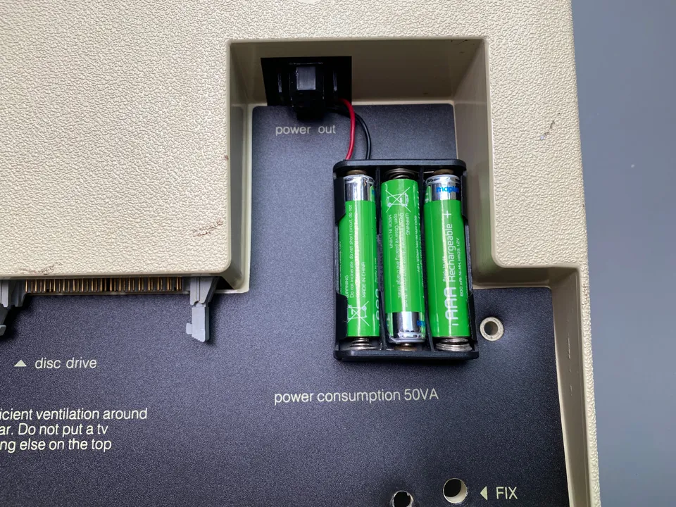
Battery pack on the bottom
With the new batteries installed I turned on the BBC Micro and ran a battery test program to check that the batteries were functioning correctly and keeping the memory intact when the computer is off.
10 REM SRAM battery backup test - bank 14
20 MODE 7
30 bank=&70:ptr=&72:pg=&73:endpg=&74:save=&75:cnt=&76:first=&78
40 DIM code% 200
50 PROCassemble
60 ?bank=14
70 PRINT "SRAM battery test - bank 14"
80 INPUT "RAM size, 8 or 16 KB ",S%
90 IF S%=8 THEN ?endpg=&A0 ELSE ?endpg=&C0
100 PRINT'"W = write test pattern"
110 PRINT "V = verify after power off"
120 INPUT "Choice ",c$
130 IF c$="W" OR c$="w" THEN PROCwrite
140 IF c$="V" OR c$="v" THEN PROCverify
150 END
200 DEF PROCwrite
210 CALL fill
220 CALL verify
230 IF FNerrors>0 THEN PRINT "Write failed: ";FNerrors;" bad bytes":ENDPROC
240 PRINT "Pattern written and checked OK."
250 PRINT'"Now switch off, wait, switch on,"
260 PRINT "then CHAIN ""BATTEST"" and choose V."
270 ENDPROC
300 DEF PROCverify
310 CALL verify
320 IF FNerrors=0 THEN PRINT "PASS - all bytes kept their values.":ENDPROC
330 PRINT "FAIL - ";FNerrors;" bytes changed."
340 PRINT "First bad byte at &";~(?first+256*first?1)
350 ENDPROC
400 DEF FNerrors=?cnt+256*cnt?1
1000 DEF PROCassemble
1010 FOR pass%=0 TO 2 STEP 2
1020 P%=code%
1030 [OPT pass%
1040 .fill SEI:LDA &F4:STA save:LDA bank:STA &F4:STA &FE30
1050 LDA #0:STA ptr:LDA #&80:STA pg
1060 .fpage LDY #0
1070 .floop TYA:EOR pg:EOR #&A5:STA (ptr),Y
1080 INY:BNE floop
1090 INC pg:LDA pg:CMP endpg:BNE fpage
1100 JMP restore
1110 .verify SEI:LDA &F4:STA save:LDA bank:STA &F4:STA &FE30
1120 LDA #0:STA ptr:STA cnt:STA cnt+1:LDA #&80:STA pg
1130 .vpage LDY #0
1140 .vloop TYA:EOR pg:EOR #&A5:CMP (ptr),Y:BEQ vok
1150 LDA cnt:ORA cnt+1:BNE vinc
1160 STY first:LDA pg:STA first+1
1170 .vinc INC cnt:BNE vok:INC cnt+1
1180 .vok INY:BNE vloop
1190 INC pg:LDA pg:CMP endpg:BNE vpage
1200 .restore LDA save:STA &F4:STA &FE30:CLI:RTS
1210 ]
1220 NEXT
1230 ENDPROC
When the program starts you select the size of the memory installed, 8 or 16Kb. The battery test program has two options, write and verify. Write writes a test pattern to the memory chips, verify checks that the pattern is still there after the computer is turned off.
I tried running the test program, and it verified the memory was working when it was powered but after turning it off and on again it showed that several bytes had become corrupted. The manual for the sideways board suggested removing the write-enable and read-enable jumpers when turning the computer off to protect against stray writes on the memory bus. I tried this but the memory was still corrupting when the computer was turned off.
One common cause for memory corruption is instability in the power supply. If the power supply is not stable, it can cause the memory to lose its contents when the computer is turned off and on again. To test this I connected an oscilloscope to the 5V and ground pins on one of the memory chips and turned the power on and off. It showed a 120μS drop in voltage when the power was turned off, just long enough to corrupt a few bytes of memory. This may have been caused by the longer wires on the battery pack limiting the current to the memory chips. To fix this I soldered a 470μF capacitor across the pins where the battery was supposed to sit on the sideways board. This would act as a buffer, stabilising any voltage drops or sudden current spikes from the memory chips.
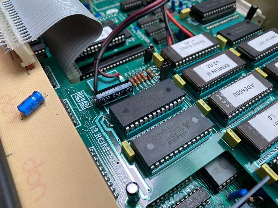
Adding a capacitor
I ran the memory test program again and after cycling the power it showed the memory was now working correctly. I ran a longer test with the computer switched off for several hours, and it showed no further corruption. It looks like adding the capacitor fixed the problem.
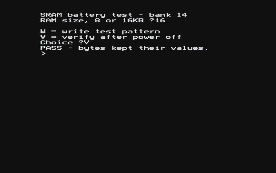
Test results look good
Final Thoughts
With the new sideways expansion board installed I have more RAM and more ROM sockets available. As well as making the BBC Micro a more powerful development environment it also gives me more options for future upgrades.
The motherboard still has space for an Econet port and a speech synthesis chip. I could also add a Terminal ROM and connect a modem to the computer for some old-school BBS action.
One issue I did notice while typing out the memory test program was the keyboard has a very annoying squeak on most of the keys. Designing a new keyboard that uses modern Cherry key switches with the original key caps may be a worthwhile upgrade.
There are some external upgrades I could make with a second processor, either 6502 or ZX80. I could also add a Teletext adapter but that would also mean finding a way to generate an RF TV signal with a Teletext feed.
There were a lot of different expansions and accessories made for the BBC Micro, so I will have to wait and see where this 8-bit journey goes next.